Super-Scalar RISCV CPU (SSRV) —— A synthesizable solution on Super-Scalar and out-of-order
A simple tutorial on SSRV
SSRV is a synthesizable verilog solution on super-scalar and out-of-order. If you are new to it, please have a look on this tutorial:
Add buffers for the result of instructions
RV32IMC instructions
SSRV divides RV32IMC instructions into 3 kinds for the purpose of super-scalar and out-of-order:
-
SPECIAL instructions:
-
MEM instructions:
-
ALU instructions:
The detailed illustration is here : >>>
A Multiple-in, Multiple-out Buffer
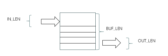
The basic component of SSRV is a multiple-in, multiple-out buffer, which has a capacity of multiple elements. FIFO is the simplest one of them. To implement complex operations, you should extend its function and be sure to manipulate it with Verilog.
It could be detailed here: >>>
Modules of SSRV
SSRV is based on and inspired by SCR1 of Syntacore. SCR1 has a complete verification and development suite. It provides a solution from C files to BIN files, and systemverilog testbench files loading BIN files to feed simulation of RTL.
SSRV will take over the authority of imem and dmem bus and testbench files do not know whether SCR1 or SSRV is fetching instructions to operate data bus. It is a good idea to have a gold model helpful to debug SSRV.
SSRV has its own testbench file: /testbench/tb_ssrv.v. It will run with the testbench file of SCR1 simultaneously. The internal signals of SCR1 are connected to SSRV directly. It can be cancelled by commenting the verilog definition “USE_SSRV” of /rtl/define_para.v. In this case, SCR1 will lead simulation and SSRV is an idle process.
In the testbench file of SSRV, an instance of SSRV’s top verilog file is listed here.
ssrv_top u_ssrv(
    .clk                    (clk                ),
    .rst                    (rst                ),
    // instruction memory interface
    .imem_req               (imem_req           ),
    .imem_addr              (imem_addr          ),
    .imem_rdata             (imem_rdata         ),
    .imem_resp              (imem_resp          ),
    .imem_err               (1'b0               ),
    // Data memory interface
    .dmem_req               (dmem_req           ),
    .dmem_cmd               (dmem_cmd           ),
    .dmem_width             (dmem_width         ),
    .dmem_addr              (dmem_addr          ),
    .dmem_wdata             (dmem_wdata         ),
    .dmem_rdata             (dmem_rdata         ),
    .dmem_resp              (dmem_resp          ),
    .dmem_err               (1'b0               )
  );
For now, SSRV is an instruction processor. It will fetch instructions from instruction memory and follow them to update the register file and operate data bus. It has a data memory interface. Load and store instructions will give different logic value on the data memory signals. If the instruction memory and data memory response well, SSRV will work well, too.
That’s the top of SSRV. Let’s review its internal and know how to implement different functions of various modules.
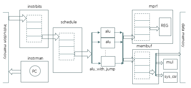
- instrman
This module produces PC for fetching instructions. It will start fetching incrementally until the buffer of “instrbits” module is full or a jump occurs. >>>
- instrbits
A preliminary buffer for instructions to store. If its instructions are accepted by the next buffer, it will remove them to save space. >>>
- schedule
It always takes incoming instructions in until the buffer is full or a SPECIAL instruction appears. It divides the union of incoming instructions and ones stored into two arrays: one is for next stage to be executed; the other is to stay the buffer. >>>
- alu/alu_with_jump
It gives ALU instructions the operation result, or MEM instructions the load/store method, address, and write data. If this ALU is the last one, it will be instantiated by “alu_with_jump”, which has the function of generate jump address for a jump instruction. >>>
- mprf
It has a buffer to store the operation result of all ALU instructions. In every cycle, it will write the operation result of instructions, whose preceding MEM instructions all retire, to the register file. >>>
- membuf
Its buffer is to store the load/store method, address and write data. Multiple MEM instructions are queued until the most preceding one have the chance to operate the data bus. If the data bus reports OK, this MEM instruction retires; or arises an exception.>>>
- mul
If a mul instruction is queued in the buffer of “membuf”, it could initialize a mul/div calculation in advance. Its operation result will be queued into a buffer. If this mul instruction becomes the most preceding one, its operation result is fetched from this buffer and dispatched to the register file. >>>
- sys_csr
Err, illegal, fencei, fence, sys instructions and csr ones are dealt with in this module. These are related with CSR registers. It could send one of CSR register to the register file for csr instructions; or arise an exception for err, illegal instructions; or initialize a jump operation for fencei, sys instructions. >>>
Every module serves one purpose that is to make the “schedule” module dispatches instructions as many as possible. The “instrbits” buffer will accumulate more instructions. The other two buffer will have to clean their reverse to welcome new ones.
How to parameterize SSRV to balance performance and area
Four multiple-in, multiple-out buffers are embedded in four different modules. Each buffer has its own role to regulate instructions. A multiple-in, multiple-out buffer has 3 parameters: IN_LEN, OUT_LEN and BUF_LEN. To define these parameters of each buffer is a good method to balance performance and area >>>
Some tips on simulation and debug
It is a good way to download the github repository and start watching signals concerned >>>