Multiple-in, Multiple-out Buffer
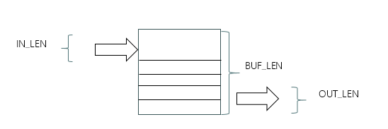
The basic component of SSRV is a multiple-in, multiple-out buffer, which has a capacity of multiple elements.
It has three parameters: IN_LEN, which defines how many elements are coming in from outside; BUF_LEN, which define the maximum elements could be accommodated; OUT_LEN, which define how many elements are going out.
Different parameters lead to different capabilities of the buffer. Because of unpredictable condition on processing instructions, this kind of buffer is very helpful in keeping instructions.
FIFO is a common buffer of this, which is always 1-in, 1-out. How to define a multiple-in, multiple-out FIFO? It assumes that “in_data” are “IN_LEN” numbers of “XLEN”-bit data, “out_data” are “OUT_LEN” numbers of “XLEN”-bit data. This FIFO is “buf_data”, which has “BUF_LEN” numbers of “XLEN” bits. We can have Verilog statements like this:
assign temp_data = buf_data|(in_data>>(buf_length*XLEN);

assign out_data = temp_data;
“temp_data” is composed of “buf_data” and “in_data”. Its length is “buf_length” + “in_length”. However, when “temp_data” is to stored to “buf_data”, its length should be “buf_length” + “in_length” – “out_length”, and data should be “ temp_data»(out_length*XLEN)” , because of outputting “out_data”.
These 3 parameters define the maximum number. IN_LEN means there could perhaps be 0,1,to IN_LEN number of elements coming to the buffer. It has an array of the length: IN_LEN. If there are 2 elements, No.0 and No.1 are valid ones and others are filled with nothing. If the input is full, No.0, No.1, to No.(IN_LEN-1) are all valid.
Here is some definitions of input arrays.
wire `N(IN_LEN)       in_vld;
wire `N(IN_LEN*XLEN)  in_instr;
wire `N(IN_LEN*XLEN)  in_pc;
“N(n)” is a Verilog definition: `define N(n) [(n)-1:0].
If in_vld is the form like this: ‘b1, ‘b111, ‘b1111, it is easy to combine it with the buffer like this:
assign temp_instr = buf_instr|(in_instr<<(buf_length*XLEN);
If in_vld is like this: ‘b101, 1’b11010, the empty “instr” or “pc” should be removed from arrays because the buffer will not contain empty ones. Here is the method to remove empty elements and form a new array without empty ones.
wire `N(IN_OFF)           cnt_num `N(IN_LEN+1);
wire `N(IN_LEN)         chain_vld `N(IN_LEN+1);
wire `N(IN_LEN*XLEN)  chain_instr `N(IN_LEN+1);
wire `N(IN_LEN*XLEN)     chain_pc `N(IN_LEN+1);

assign     cnt_num[0] = 0;
assign   chain_vld[0] = 0;
assign chain_instr[0] = 0;
assign    chain_pc[0] = 0;

generate
genvar i;
for (i=0;i<IN_LEN;i=i+1) begin
    wire              vld = in_vld[i];
    wire `N(XLEN)   instr = in_instr>>(i*XLEN);
    wire `N(XLEN)      pc = in_pc>>(i*XLEN);
    wire `N(IN_OFF) shift = vld ? cnt_num[i] : IN_LEN;

    assign cnt_num[i+1]     = cnt_num[i] + vld;

    assign chain_vld[i+1]   = chain_vld[i]|(vld<<shift);

    assign chain_instr[i+1] = chain_instr[i]|(instr<<(shift*XLEN));

    assign chain_pc[i+1]    = chain_pc[i]|(pc<<(shift*XLEN));

end
endgenerate
Eventually, there are new arrays: chain_vld[IN_LEN], chain_instr[IN_LEN], chain_pc[IN_LEN], which are the result of removing empty elements. We use a standard: in_vld[i]==1 to screen original arrays. Elements of “in_vld==0” is abandoned by getting a shift: IN_LEN, which makes the empty element beyond the boundary of the array. Anyway, if elements of “in_vld==0” need be kept, we can have another “cnt_num[i]” to give each of them a shift number and they will gather to be a new array.
The Verilog style of describing the multiple-in, multiple-out buffer here will lead us undstanding how to fliter an array or split this array into two different arrays. It is a necessary method to manage an array.
Let’s consider how to connect two buffers. Their connections can have 3 styles.
- Orphan mode
When the slave is sure that it could contain the maximum of incoming, the slave give a signal of fetching to the master. No matter how many is coming actually, there is no problem of overflow. The slave is initiative and the master does not need to know how many elements are kept in the slave.
- Mother mode
The master is initiative and it will always give the slave elements as many as possible. The slave should answer how many are acceptted acutally. The master will abandon them and make sure that it will send the closest elements in the next cycle. There is an interaction between them.
- Father mode
The master is aware how many elements are needed by the slave. It will send adequate number of elements to the slave. There is no interaction and the slave just accepts its coming elements. The slave need not worry about overflow.
These 3 styles are all used in SSRV.
The buffer of “instrbits” will store instructions from instruction memory. It fetches instructions when the empty space of this buffer is enough. Its connection to the instruction memory is a style of “orphan” mode.
The buffer of “instrbits” will provide instructions to the buffer of “schedule”. The module “schedule” will try to issue instructions as much as it can, but it will not be sure how many are issued successfully. It needs the buffer of “instrbits” gives the maximum number of instructions, and it will return how many are issued to the next stage or kept in its buffer. The connection between them is “mother” mode.
The module “schedule” is aware of the empty space of both the buffers of “membuf” and “mprf”. They are necessory to help it issue how many “OP/OP-IMM” instucutions or “MEM” instructions. It will make sure that its schedule is satisfied by all its slaves. The buffers of “membuf” and “mprf” need not consider the problem of overflow and it is a problem of the module “schedule”. Their connection is “father” mode.