Add buffers for the result of instructions
From the last section, we know how a simple processor model works. It has two different kinds of instructions: LSU ones and OP ones. LSU instructions need a protocol of visiting data memory, which at last has two cycles: request and acknowledgement. Some slow implementation of data memory maybe needs more cylces between them.OP instructions have immediate operation of registers. They could be executed immediately if the register file is ready.
The different of LSU and OP instructions leads to pauses of the pipeline when LSU instructions are being executed. The acknowledgement cycle of LSU instructions is extra to suspend the pipeline.
Let’s take an example:
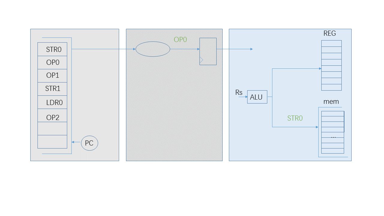
After the instruction “STR0” reaches the 3rd stage, it will stay for 1,2 or more cycle to wait for the acknowledgement signal from data memory. During these cycles, the instruction “OP0” could be executed because the register file is intact. However the result of “OP0” is not allowed to go into the register file until “STR0” gets its successful acknowledgement. If the result of “OP0” is written to the register file and it reports error acknowledgement, there is no way to recover the register file because the exception invoked by this memory error assumes the register file keeps the status before it is executed.
There is a way to make “OP0” be executed in advance, which is a buffer for the result of the following OP instructions. “OP0” could fetch its Rs and have its result generated by Rs and its immediate operand. This result could be stored in a buffer close to the register file. If “STR0” reports successful, this result will update its Rd of the register file immediately. If it is a failure, this buffer is cleaned.
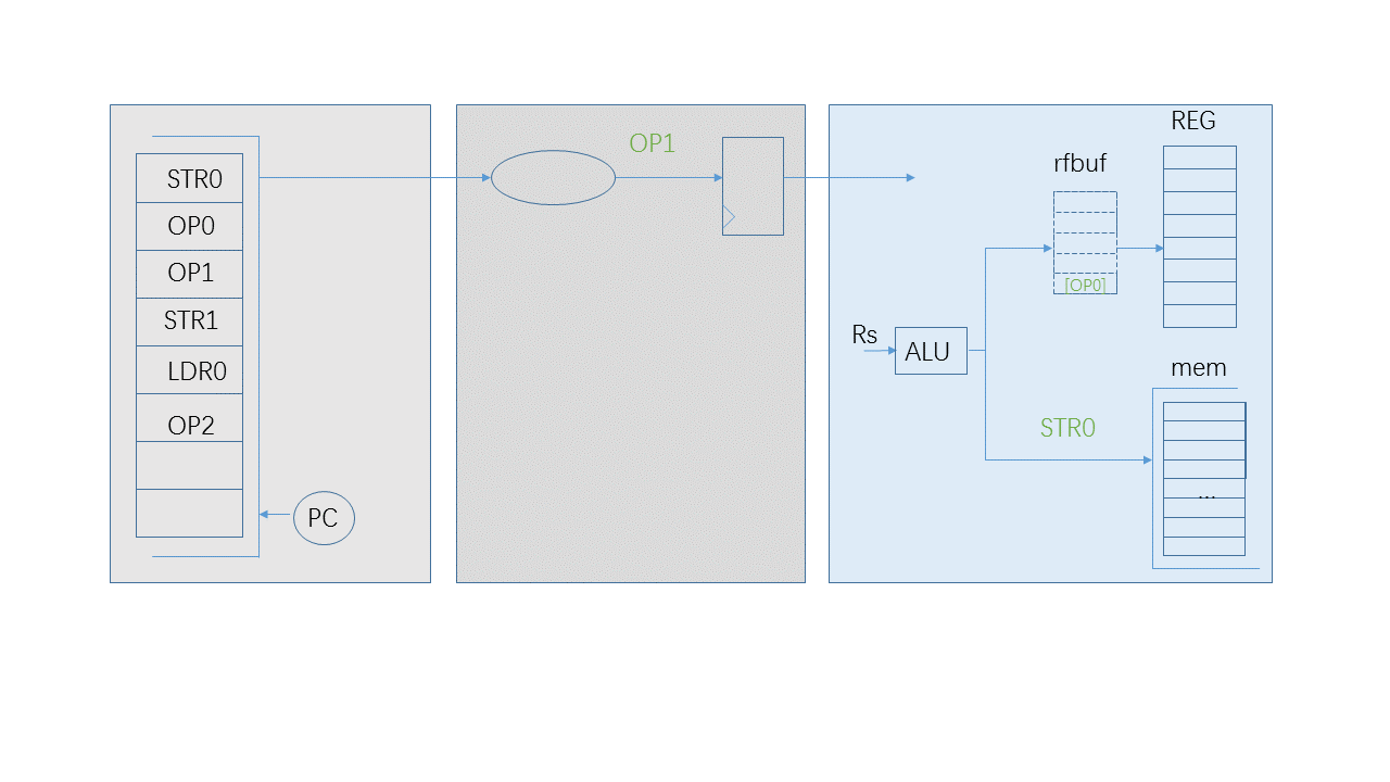
When the pipeline is stalled by the “STR0”, “OP0” could be executed and there is also a chance for the next instruction: “OP1”. “OP1” could be executed and its result could be placed to the “rfbuf” after the result of “OP0”. It is not enough to fetch its Rs from the register file because maybe its Rs is being updated by “OP0”, which means Rs of “OP1” is equal to Rd of “OP0”. in this case, fetching Rs includes two steps:
- get Rs from the register file.
- Check every valid elements of “rfbuf”. If there is an update of Rs, replace it.
In this way, the instruction “OP” is converted to the different form: its Rd number and its result of calculation. “OP0” and “OP1” are closer to retire. They are waiting for the successful message of data memory. When it arrives, these two updates could be executed immediately. We could say that there instructions: “STR0”, “OP0” and “OP1” retire in the same cycle.

Let’s do more. Why not a buffer for LSU instructions? When “STR1” in the diagram is ready, it will have this question. It could fetch its Rs from the register file and the “rfbuf” buffer. It could have its address and write data prepared. We can cache its operation information and save the pipeline for the next instruction.
Anyway, A “LSU” instruction is different from a “OP” instruction. The “LSU” instruction is a specific operation on data bus. “rfbuf” could cache the result of Rds of instructions, but the buffer “mmbuf” for “LSU” instructions will not be so convenient. It has to cache mixed operation elements:
- Operation parameter: such as byte, half-word or word store.
- Operation address: the result of Rs0 and its immediate operand.
- Operation write data: Rs1
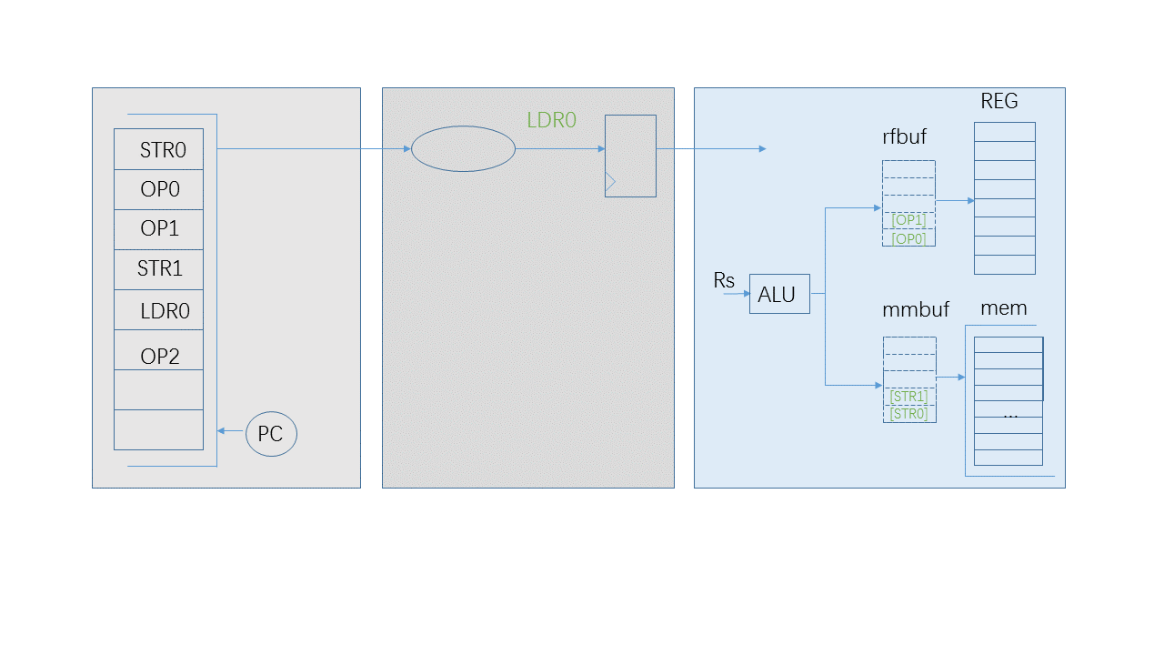
The buffer “mmbuf” of “LSU” instructions could also cache “LDR” instructions. When a “LDR” instruction is cached, it has an implicit message: Rd of “LDR” will be updated by read data from data memory. In the diagram, when “LDR0” is accepted by “mmbuf”, there should be a blacklist check for the following instructions. Because every instruction has two factors: Rs and Rd, “rs_list” and “rd_list” are two blaclists, which are filled by Rds of “LDR” instructions.
If Rs or Rd of the following “OP2” instruction match the blacklists, the pipeline should be stalled. “OP2” could not be issued to “rfbuf”.
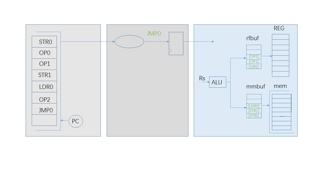
If it doesn’t match, the result of “OP2” could be qualified to go into “rfbuf”. However there is an issue arose, which is that when the successful acknowledgement of STR0 is coming, “OP2” should not retire as the same as “OP1” or “OP0”.”OP2” should stay in the “rfbuf” buffer until its leading LSU instruction “LDR0” gets a successful message, in case that “STR1” or “LDR0” has a possibility to bring an abort exception.
It is necessary to give every element of “rfbuf” an order to make them retire gradually. The simplest way is to give every new member of “rfbuf” an order, which means how many elements exist in “mmbuf” when it enters.
| STR0 | OP0 | OP1 | STR1 | LDR0 | OP2 | JMP0 |
|---|---|---|---|---|---|---|
| 1 | 1 | 1 | 2 | 3 | 3 | 3 |
When “STR0” is waiting for its acknowledgement, “OP0” and “OP1” has its order: 1 and “OP2” has its order 3. If the data memory releases one successful message, the order of every element of “rfbuf” decreases 1 until it reaches 0. If the successful message of “STR0” comes, “OP0” and “OP1” has a new order–0, which means they have an authority to write to the register file and “OP2” has a new order–2. Then that “STR1” retires will make the order of “OP2” become 1. Until the nearest leading LSU instruction “LDR0” retires, “OP2” will have an order 0 to gain the authority to go into the register file.
However, if any of LSU instructions brings an exception, it has to apply a new policy to “rfbuf” that if the order is zero, keep it; if the order is not zero, clean it.
There is an interesting scenario to be present when the following instruction “JMP0” is executed. The instruction “JMP0” will assign PC to a new target address and the target instructions will arrive to the pipeline. If “STR0” is still waiting its response, the target instructions will join the two buffers separately. Each of the two buffer is mixed with new and old instructions. If every elements of the LSU buffer “mmbuf” leaves smoothly, the two buffers will maintain a good order to push newcomers and pop leavers.
Since there is only one interface to the data memory, the “mmbuf” will pop one element if the data memory gives one successful response. In most of data bus protocols, the request of the successor and the acknowledgement of the leaver could be overlapped in the same cycle. The “rfbuf” buffer could pop multiple elements of the zero order.
The two buffers added are very helpful to accommodate instructions. When the pipeline is stuck by LSU instructions, it could be taken advantage of by issuing the following ones to these two buffers. The next section will discuss how to output more instructions from the 2nd stage.