A simple processor model
First of all, Let’s have a very simple processor model. It has 4 kinds of instructions.
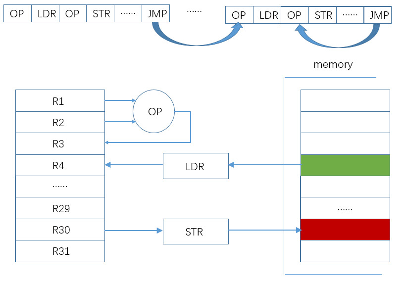
Each of these has a different function:
| Instructions | Rs(input registers) | Rd(output register) | Operation |
|---|---|---|---|
| OP | Rs0/1 | Rd | Change of some register |
| LDR | Rs0 | Rd | Fetching from mem and writing to Rd |
| STR | Rs0/1 | N/A | Writing Rs1 to mem |
| JMP | Rs0/1 | Rd | Change of some register and PC |
These 4 kinds of instructions are necessory for all RISC processors. we should review their manner of dealing with data.
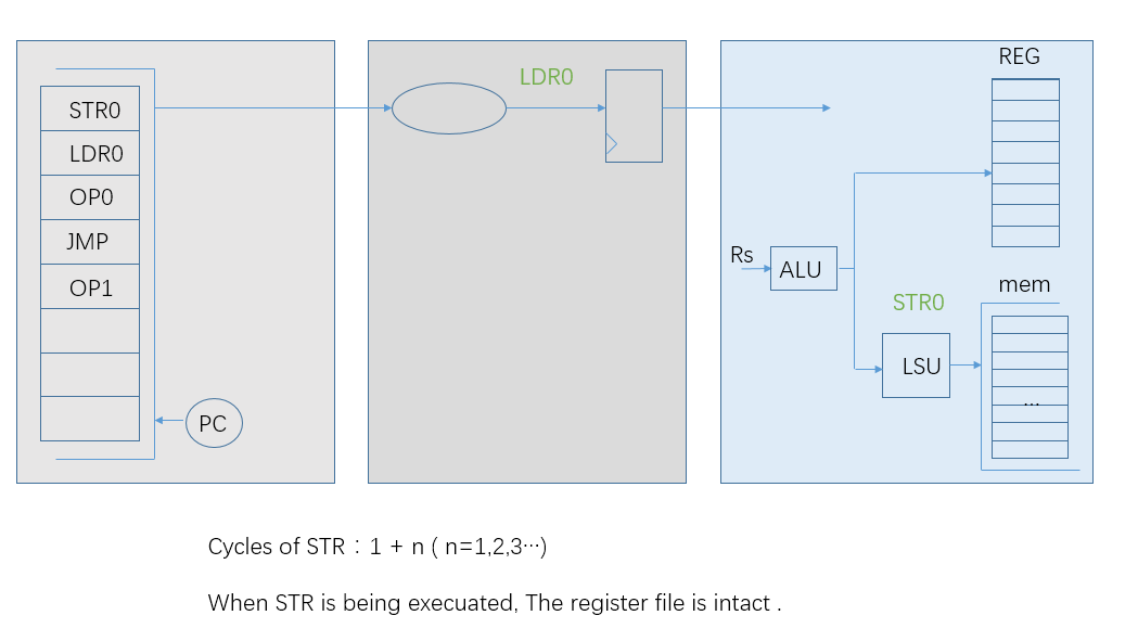
STR
This kind of instructions is to transfer some register to the location of the data memory, which is defined by the addition of the register Rs and an immediate operand.
Let’s explain every instruction in a 3-stage pipeline.
-
In the first stage, this “STR” instruction is stored in some location of instruction memory. The processor or core gives its address to the instruction memory.
-
In the second stage, this “STR” instruction is present on the data bus of the instruction memory. The processor will decode it to get miscellaneous signals.
-
In the third stage, the “STR” instruction has at least two cycles to fulfil its task.
-
It Fetches its Rs0/1 from the register files. Rs0 is used to get the address and Rs1 is the data of the store operation. In this cycle, it initializes its store request with its address and data.
-
After N(N=1,2,3…) cycles, the data bus reports its acknowledgement of the store operation. If it is successful, the “STR” instuction retires. Or, a “STR” exception is forwarded to the system module. The system module will hault the execution of following instructions and jump to the exception entry to deal with that. The exception entry assumes that the register file is not overrode by the “STR” instruction and its following ones.
-
LDR
This kind of instructions is to load data from data memory and write it to some register.
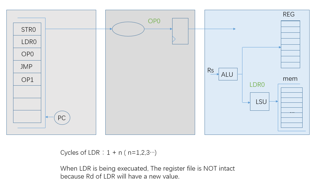
All 4 kinds of instructions share the same 1st and 2nd stage. In the 3rd stage, “LDR” has two or more cycles to fulfil its request and acknowledgement.
-
The request needs its address to the data memory. It is the addition of the register Rs0 and an immediate operand.
-
After the request, the data bus reports its acknowledgement and presents data that is requested by “LDR”. When it is successful, data is written to the register Rd of “LDR”, or abandoned. The failure leads to a jump to the exception entry.
Different with “STR”, “LDR” have an expected change of the register: Rd.
OP
“STR” and “LDR” are instructions on interchange between data memory and the register file. “OP” instructions are only related with the register files. They fetch operands from the register file and write the result to it.
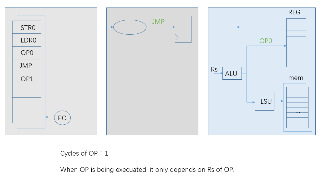
In the 3rd stage, “OP” instruction only needs one cycle to fetch operands and write the result back. The operation could be arithmetic or logical. Whatever it is, “OP” instructions will not be stuck by acknowledgement outside.
JMP
This kind of instructions will change PC and turn to other sections. It acts like “OP” instructions, just different from that Rd is a special register: PC. However, some “JMP” instruction may have an extra writing to Rd of the register file.
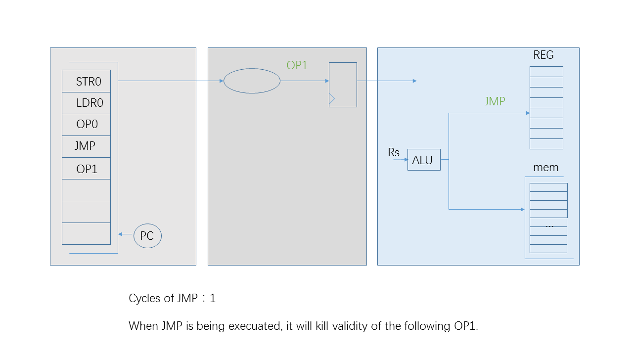
In the 3rd stage, it has to kill the execution of the following instruction when it is not a conditional one or the conditional result is true. The simplest way is to flag the validity of the following instruction as false.
If one “JMP” instruction initializes its request as soon as it reaches its 3rd stage, its target instruction will arrive to the 2nd stage at the next cycle. Since it is a 3-stage pipeline, there is a gap between the “JMP” instruction and the target one, which is the false “OP1” in the diagram.
It is a simple processor model. It has four kinds of instructions. Two are involved with data memory, which have a request cycle, an acknowledgement cycle and indefinite waiting cycles. The other two kinds of instructions are dependent on the register file. If every register is deterministic, they will be executed in one cycle.
All instructions share the same ALU module, which provides arithmetic or logical result for OP instructions and arithmetic address calculation for LSU instructions. As for a LSU instuction, the ALU is busy in its request cycle and idle in waiting or acknowledgement cycles. In the next section, these idle cycles should be utilized to improve throughput of instructions.